Alex Alexiou. Technical university of athens
The paper GT2012-69433 entitled “MODELLING CONTRA-ROTATING TURBOMACHINERY COMPONENTS FOR ENGINE PERFORMANCE SIMULATIONS: THE GEARED TURBOFAN WITH CONTRA-ROTATING CORE CASE” written by Alexiou, Roumeliotis, Aretakis, Tsalavoutas and Mathioudakis from the Laboratory of Thermal Turbomachines at the National Technical University of Athens was presented at the ASME TURBO EXPO 2012 Conference in Copenhagen, Denmark and received the Cycle Innovations Committee Best Paper Award. The paper is also published in the ASME Journal of Engineering for Gas Turbines and Power. The simulations described in the paper have been performed with PROOSIS v2.6.0. An extended abstract of the paper is included below.
Some of the current and future engine configurations contain contra-rotating turbomachinery components (fans, propellers, compressors and turbines). because of certain advantages they have compared to the corresponding conventional ones (e.g. lower engine size and weight, increased efficiency and thrust-to-weight ratio, lower noise).
There are currently only a few studies available in the public domain dealing with the subject of performance modelling for engine configurations containing contra-rotating turbomachinery components. In these studies though either a basic design point analysis is presented or any off-design analysis is carried out assuming conventional component performance characteristics. Hence, the objectives of the paper are to first derive physics-based performance characteristics of contra-rotating turbomachinery components then develop in PROOSIS component models that use these characteristics and finally, integrate these components in an engine performance model.
The first step for generating the performance characteristics is to obtain a rough estimation of the design parameters (e.g. blade angles) through a velocity triangles analysis. Then modified 1-D mean line analysis codes are employed that take into account flow angle deviation and pressure losses through empirical correlations from cascade experimental data. Finally, the flowpath and blade geometry are further refined by applying basic design rules (e.g. flow coefficient, pressure rise coefficient, De Haller number) and previous experience from existing conventional compressors and turbines.
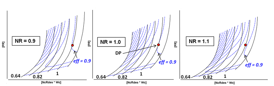
Having established basic geometric data for the contra-rotating components, the corresponding performance maps are generated in the form of three-dimensional tables (maps). Compared to conventional turbomachinery component maps, the speed ratio (NR) between the two shafts is included as an additional map parameter and the torque ratio as an additional table. The maps corresponding to the 7-stage contra-rotating compressor and two-stage contra-rotating turbine of the test case configuration are presented in the following figure for three different values of speed ratio (NR = 0.9, 1.0 and 1.1).
 Contra-Rotating Compressor Map For Different Values of Speed Ratio
 Contra-Rotating Turbine Map For Different Values of Speed Ratio
Dedicated component models are then developed in PROOSIS that use these maps to simulate design and off-design operation at component and engine level. For configuration and version control purposes, the contra-rotating components are developed in a dedicated library which acts as an extension of the PROOSIS standard TURBO library since it is allowed to use all its components and ports. As the basic compressor and turbine functionality is common for conventional and contra-rotating components and taking advantage of the abstraction and inheritance properties of the object-oriented simulation environment, only the code related to the contra-rotating part needs to be described in the new library.
Using these components, a performance model of a geared turbofan with a Contra-Rotating Core is created. This configuration was investigated in the context of the European program NEWAC. In this arrangement, the compressor comprises an inner rotor (like in a conventional case) and an outer rotor so that successive blade rows can rotate in opposite directions. The rotors are driven by a contra-rotating turbine through two concentric drive-shafts, as shown in. the schematic diagram below:
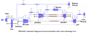 PROOSIS Schematic Diagram of Geared turbofan with Contra-Rotating Core
The engine model is then coupled to an aircraft performance model and a typical short-range mission is carried out. The results are compared against those of a similar configuration employing a conventional core and identical design point performance. For the given aircraft-mission combination and assuming a 10% engine weight saving when using the Contra-Rotating Core arrangement over the conventional one, a total fuel burn reduction of 1.1% is predicted. If the engine weight saving is used to increase payload then a total of 3.2% fuel burn reduction per 100 passenger kilometre can be achieved. Further benefits could have been predicted if a lower amount of turbine cooling flow was assumed for the Contra-Rotating Core since there are reduced cooling and sealing requirements in this configuration as there is no stator between the two turbine rotors.
The methodology described in the paper is not application specific and is also relevant to contra-rotating turbofan and contra-rotating open rotor cases. Higher fidelity codes or experiments can be used to generate more accurate physics-based performance characteristics for the contra-rotating components – the integration of the maps can be performed in the same way.