The CONTROL library, supplied with the professional version of EcosimPro, facilitates the robust, fast design of control diagrams for multidisciplinary digital and analogue systems: hydraulic, thermal.
Moreover, it provides ample functionality for handling signals. It can be used as a stand-alone library or together with other libraries.
Thanks to EcosimPro’s features, the CONTROL library is very easy to configure and extend, adding any components and characteristics as needed. This can be done graphically through a simple, user friendly interface, or through EcosimPro’s object-orientated language which makes it possible to re-use existing codes.
The library has a wealth of components with which to model any current control structure covering analogue, digital and mixed systems. There are specialised components in both fields and converters from one to the other.
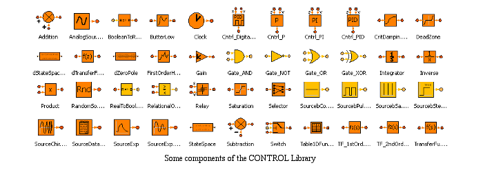
These components are established in different groups will be established and included in the Control library with several representative examples:
- Signal generators: The input possibilities cover classic forms of excitation such as a stepped input, ramp input, staggered input, exponentials, frequency variators… including stochastic signals based on different distributions (Normal, Gaussian, Poisson,…) and different data reading functions and their interpolation into tables defined by the user via files so that any pattern can be established
- Signal handling: There are different functionalities for handling signals by means of switches, comparators, multiplexers, demultiplexers, or they can be handled through operations such as add, inversion, integration, bypass, trigonometry functions
- Signal transformation: Transformation of the type of variable (Boolean to real), samplers, holders, filters, delays
- Logic gates: To create Boolean logic diagrams, we have AND, OR, NOT, XOR gates
- Controllers: The components P, PI, PID are highly configurable contemplating the phenomena experienced with current controllers, such as anti-windup, deadband, saturation to different internal levels of the component, filtered
- Modellers: Finally, the plant to be controlled can be modelled by external libraries, or using their representation by means of transfer functions, status spaces, zero-pole
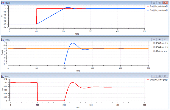
A very simple case where the PI component of CONTROL library is used to control the level of a tank is presented. The controller can be easily configured through the Attribute Editor in order to modify the main characteristic data (gain, integrator time, limits…)
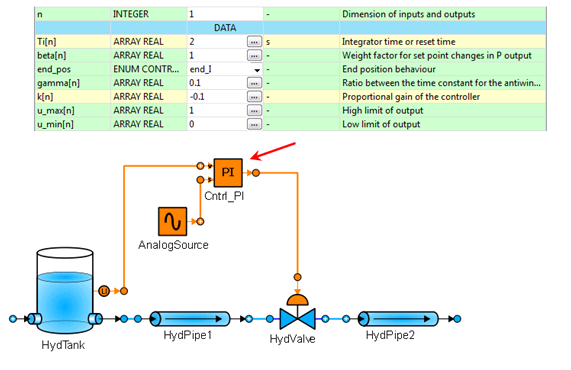
When the set point of the level is increased, the PI controller closes the valve until the level reaches the new set value. Then, the controller opens the valve and the mass flow increases in order to maintain the required set point.
The CONTROL library has been used in complex control system as in a boiler. It consists of three control systems: feed water mass flow, steam pressure and steam temperature.
Each control system has been encapsulated in macro-components (represented by orange squares).
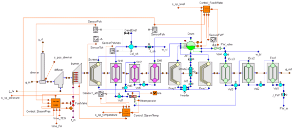
Then, the steam pressure control model is described more in detail. The objective of this control loop is to maintain the steam outlet pressure in the desired level. The control model consists basically of the following parts:
• Three PI master controllers charged on the steam pressure control, burner temperature limitation and steam mass flow limitation respectively.
• A set of look-up tables interpolating the maximum fuel flow as a function of time.
• A set of fuel valve positions will impose directly the fuel valve position.
• The slave controller that regulates the fuel valve position receives as set point the minimum of the master controls and the look-up tables.
Finally, the slave controller output is limited to a minimum value by means of the MinvalvePos component to guaranty a minimum steam flow production.
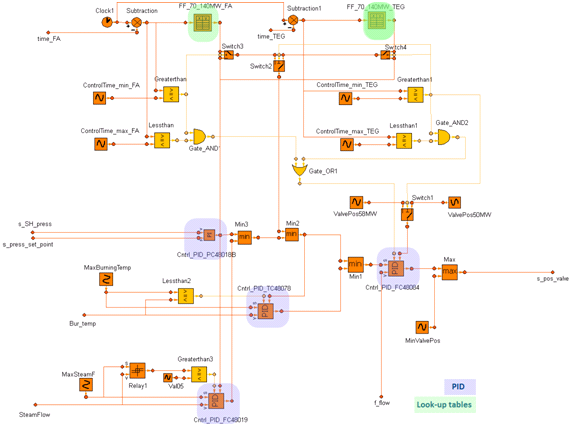
Schematic of the steam pressure control model
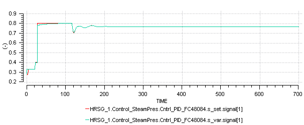
The following results are obtained when, at time = 0 s, a trip of TEG (Turbine Exhaust Gas) to FA (Fresh Air) change over is activated. The next figure shows the pressure evolution in both boilers.
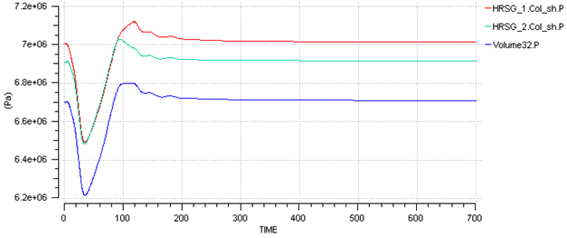
Regarding the control variables evolution of the pressure control model, the above figure represents the main variables: set point, measured signal and output signal.
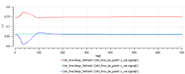
And the fuel flow responsible for maintaining the pressure in the boilers increased its set point.
The following model has been used for this example,
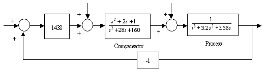
and its representation in EcosimPro is illustrated in the following diagram:
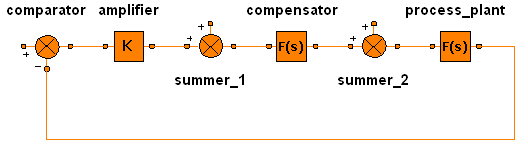
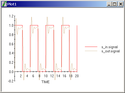
After the corresponding component was generated, a “linear_exp” experiment was run to simulate the system response for 20 seconds for a 5 second square wave input signal.