The ELECTRICAL library powered by Ecosimpro provides a comprehensive solution for simulating electric and electronic systems. With its easy to use drag & drop methodology, the library enables users to quickly model in the digital world, systems and components that are almost identical to their physical counterparts. This library offers a wide range of functionalities, from simulating power distribution networks and transformer stations, to power electronics and digital electronic elements. Thanks to its object-oriented language, it’s easy to configure and extend, allowing users to add components and adjust characteristics to their design. Additionally, the library’s modular design allows users to encapsulate components into a single subsystem and share tasks among specialised users, making the entire process of modelling and simulating simpler and faster.
Features
Using drag & drop methodology, the user can quickly create the wiring diagram to be analysed, the representation of which is very similar to the physical system. The library has a wealth of possibilities, ranging from the simulation of power distribution networks and transformer stations to power electronics and digital electronic elements.
Thanks to EcosimPro’s features, the ELECTRICAL library is very easy to configure and extend, adding any components and characteristics as needed. This can be done graphically through a simple, user friendly interface, or through EcosimPro’s object-orientated language which makes it possible to re-use existing codes.
Applying the object-oriented methodology, a group of components can be encapsulated into a single subsystem used like a black box, with a defined number of inputs and outputs. This enables modular design of the overall system and makes it possible to share tasks among different specialised users or merely simplify the system.
The most important features of the library are:
- The most basic two- or four-pin components are programmed based on Ohm’s law (resistance devices), ‘Faraday’s law (devices storing energy in an electric field), and Henry’s law (devices storing energy in a magnetic field).
- Special components simulating Amplifiers, RC lines, Switches, Diodes, Transistors and Electromotive Force are included.
- Generic sources of current and voltage are included.
- Sensor components measuring the current and the voltage in a branch (which allows coupling electrical circuits to control blocks) are also available.
Components
Different component groups are established and included in the ELECTRICAL library with several representative examples:
- Signal generators: The input possibilities cover the classic forms of generation: voltage and direct current supplies — senoidal, trapezoidal. There are voltage, current, voltage-current and current-voltage convertors. There are also two very interesting components, generators of current/voltage signals that track a control signal, which greatly expands the input possibilities
- Passive elements: In addition to the classic elements: inductors, resistance and ideal capacitors, there are other components specialised in electric transmission: Lossy transmission line and uniform distributed RC line, transformers, ducting and shortcircuits
- Active elements: The library contains the main semiconductors: diodes (they take temperature into account), NMOS transistor, PMOS transistor, NPN transistors, thyristors and operational (ideal) amplifiers. By changing their parameters, these elements can be used both as power and electronic components
- Signal handlers: There are ideal circuit breakers and switches
- Sensors: The library can be directly connected to the control library by means of the current, voltage and power sensors. These can be considered as variables to be controlled or as system control parameters
- Power transformation: Finally, a component to transform electrical energy into rotational mechanical energy has been contemplated. It is used as the basic building block for an electric motor.
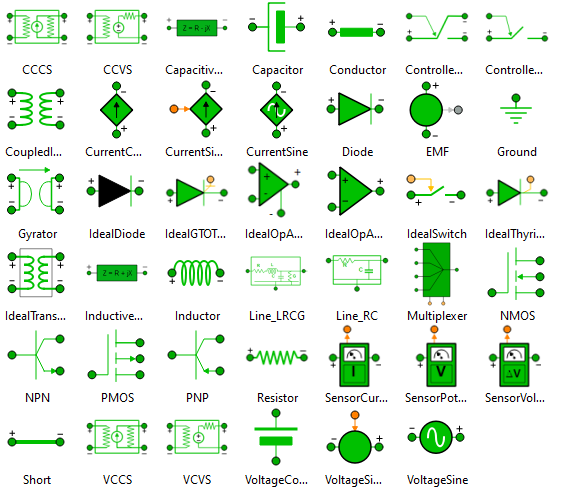
ELECTRICAL library palette of symbols:
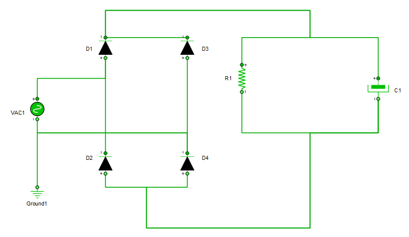
A diode bridge is used to rectify a signal. Given that the diode acts as some sort of valve, an oscillating signal can become constant in value.
This model represents a diode bridge built as shown below:
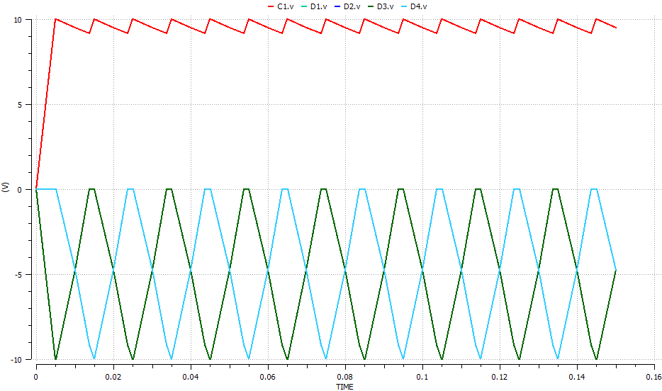
For this example, an experiment “exp1” has been created which consists in integrating 150 milliseconds with a 10 V 50 Hz alternate voltage generator in which the original generator signal and the signal rectified by the diode bridge can be seen.
The monitor shows how the diodes with aid from a capacitor turn the sine wave into some sort of sawtooth signal. The drop in voltage seen between peaks is caused by the capacitor discharging itself before charging again.