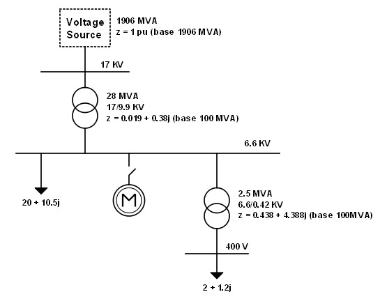
The user case that is shown here models a real pumping system. The pumps are actuated by means of 2500 KW/ 6600 V induction motors. The motor is fed through a 28 MVA and 17/6.9 KV transformer. The main 17 kV busbar has a power of 1900 MVA. This user case can be summarised by means of the following general diagram:
The available components in the ELECTRIC-SYSTEMS toolkit are used to create the following model for the relevant components, and their parameters are configured in accordance with the documentation provided by the manufacturers:
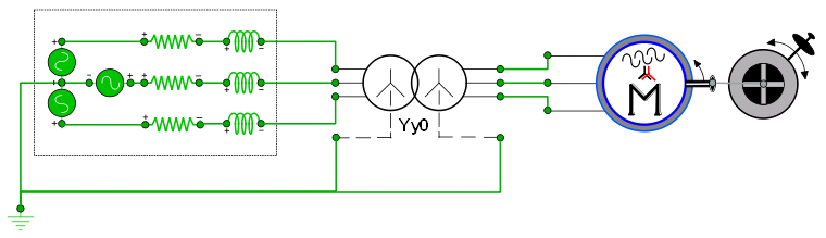
The limited power of the main busbars with the corresponding output impedances. On the other hand, a three-phase transformer with a star-star connection has been used. The motor used is of double squirrel cage rotor type, and the pumps have been modelled by means of the equivalent mechanical load. The dynamic nature of the library allows the startup transients to be simulated and the behaviour of the main system electrical and mechanical variables during critical processes to be analysed.
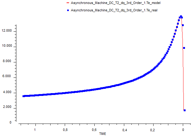
The following figures show, in this order, the behaviour of the shaft speed, the phase current used, the torque generated by the motor and the voltage drop in the 6600 V busbars during the startup process:
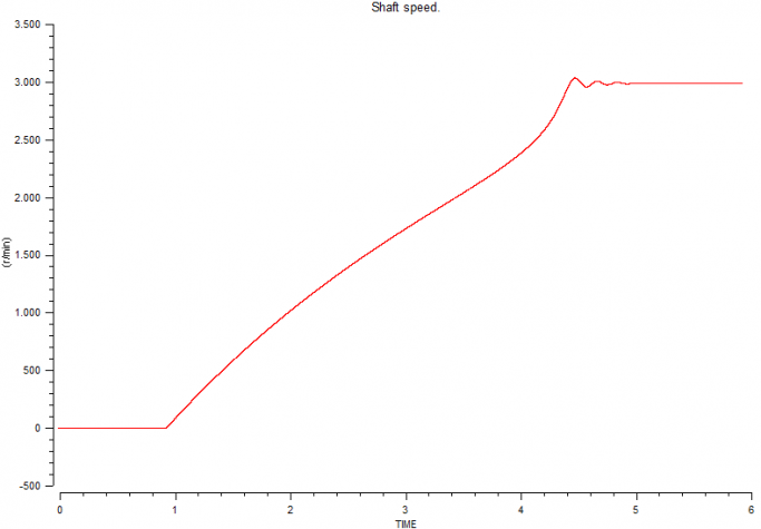
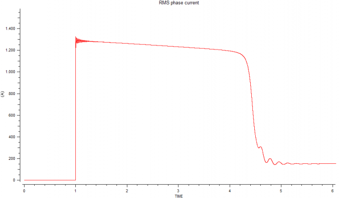
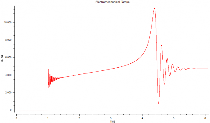
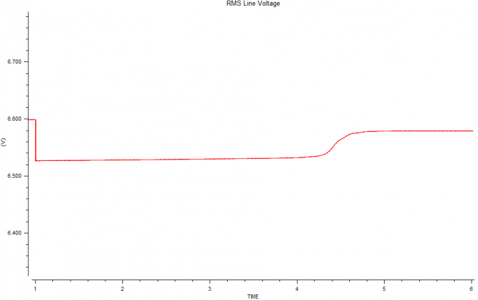
The system is connected in TIME = 1s. The motor uses its maximum power during the acceleration stage, causing a voltage drop in the supply busbars. The highest torque peak occurs once the motor reaches its rated speed. Finally, the system is stabilised, the torque drops and the current is reduced to its rated values as the busbar voltage is recovered.
EcosimPro/PROOSIS includes a powerful optimisation and tool and to estimate parameters that may come in handy to adjust the configuration parameters of the electrical models. Thus, the main motor parameters for the case in the above example were identified.
The EcosimPro/PROOSIS parameter estimator analyses the response curves provided by the manufacturer, taken from real systems or estimated by means of verified procedures. Once these curves are associated to the behaviour of certain model variables, it can provide values for certain component parameters that allow the response that is closest to the reference to be obtained. In the case of induction motors, the torque/slip curves are normally the most common in the market. Furthermore, sometimes startup curves are available for the speed and current.
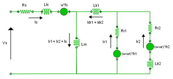
The data available from the above example was used to complete an estimate of the main motor parameters. To do this, the torque/slip curve was used during a first stage. The process was later repeated using the startup torque curve generated by the dynamic model to more accurately obtain the values of the resistors and inductances in the equivalent model of the motor based on the system oscillations. The model of the double cage induction motor can be represented with the following equivalent circuit:
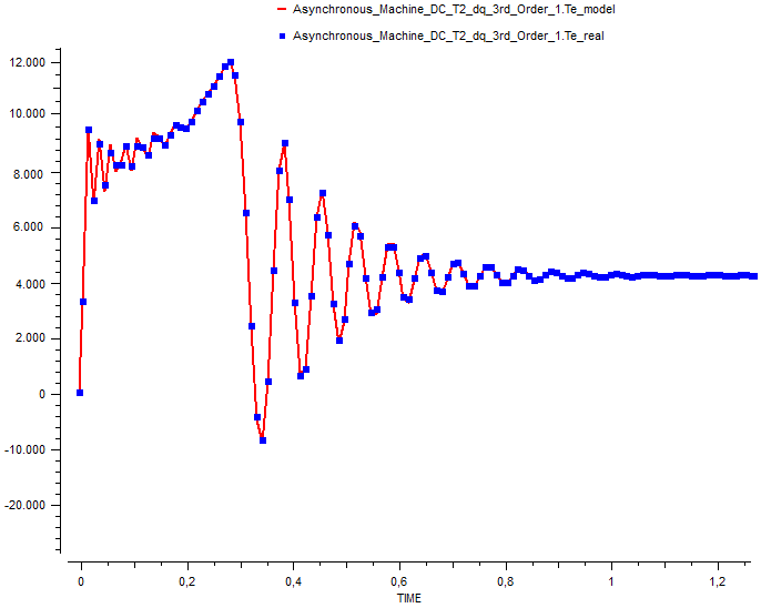
The curve for torque versus time in the dynamic startup model showed the following adjustment for the estimated set of parameters:
For this set of values, the result obtained for the torque/slip curve is shown in the following figure:
The SMART-GRID library provides the necessary capabilities in order to model and simulate renewable energy and smart grid systems with EcosimPro. The library has been developed keeping the compatibility with the rest of EcosimPro libraries, especially ELECTRIC-SYSTEMS, CONTROL, MECHANICAL, etc. Initially, the library includes components for modelling photovoltaic and wind generation systems, diesel backup and batteries for energy storage. The necessary control and management components are also included in the library. In the future, additional elements will be added such us hydroelectric generation, fuel cells or solar thermal energy.

Photovoltaic panels
The solar photovoltaic panels have been modelled combining schematic modelling with ELECTRICAL library components and EL code for additional aspects such as aging or thermal behaviour. The model allows the user to modify a wide variety of parameters such as the number of cells and panels of the facility, electrical values, efficiency or thermal influence coefficients. The following figure shows the photovoltaic solar panels model in SMART-GRID library:

Parametric studies can be performed effortless in design stage before wider systems modelling and simulation. Through these studies, the user will be able to generate the typical power and current curves versus solar irradiance and polarization voltage according to the panel configuration. The following figure shows the photovoltaic solar panels current and power curves:

Wind generator
The wind generator model has been created topologically combining several components also included in the SMART-GRID library.

The main component is the wind turbine itself, which extracts a certain amount of energy from the available wind according to the user configuration through different parameters. Similar to the solar panel, parametric studies can be executed over this component, generating the well known wind turbine performance curves:

The wind generator schematic model described here includes also a drive train, a synchronous generator, an AC/AC converter for variable speed operation and other control systems for safety and performance objectives. However, the user will be able to create other topologies using SMART-GRID library components in combination with ELECTRIC-SYSTEMS library components: synchronous machine with variable excitation, doubly fed induction machine, etc.

The wind generator model can be also resized by the user defining a whole farm from the same base component.

Batteries
SMART-GRID library includes also a battery model for energy storage purposes.

It has been modelled through the EcosimPro interpolation capabilities. To do so, the Voltage – State Of Charge dependence has been defined and a second dependence of the electric current sign has been introduced thereby considering electrical transients.

The nominal electrical parameters and the battery array size can be also dimensioned by the user. In future versions of the library, other aspects like aging or thermal influence will be considered.
Diesel Generator
SMART-GRID library includes also a diesel generator model for energy back up. It will provide the frequency and voltage level for the local grid when operating in island mode.

The model has been created combining MECHANICAL, CONTROL and ELECTRIC-SYSTEMS components. Control loops have been created to warranty frequency and output voltage values through mechanical torque and field excitation voltage regulation. In future reviews, additional aspects will be included, such us fuel consume and non linear torque response for the diesel engine.

Environmental conditions
Renewable energy generation is closely related to environmental conditions: Solar irradiance, temperature and wind speed. These aspects can be introduced in SMART-GRID models by the Environmental_Conditions component.

The user can introduce simple behaviours like constant values, steps, ramps and other typical shapes. Additionally, other customized behaviours can be defined by data tables which will be interpolated according to TIME values. External files with real weather measurements can be also accessed from this component for interpolation. In order to avoid non-real fast changes and noise in measurements, customizable filters are included for the three weather variables.
Converters, controllers and power balance
SMART-GRID library components need several controllers and converters to work in combination since some of them are AC systems, others are DC systems and in general, all of them must adjust their behaviour to the circumstances of the grid. That is why the library provides also a wide variety of converters, controllers and power balance components.

It is worth mentioning the master controller task, which is in charge of warranting that the energy generation is optimized trying to reduce fuel consumption as much as possible, and the local grid component, which includes the power balance equations and determines the energy deficit or excess.
Test case
In this first test case, a system consisting of a solar photovoltaic power plant, a wind power farm, a diesel support unit and a battery storage system has been modelled. The developed model simulates the typical consumption during a day in an average facility. An analysis is made to establish how to obtain that energy by reducing the contribution from the diesel generator to the minimum. The system will be managed on a global scale by a master controller in charge of optimizing the generation-storage process to best meet the demands. The environmental conditions, the power demand profile itself and the configuration of each element are open so that they can be easily modified by users. The figure shows the schematic model developed in EcosimPro.

The power balance curves show how the energy generation is satisfied from renewable sources mainly, using only the minimum necessary diesel generation. Also over and miss generation processes have been scheduled in order to charge and discharge the batteries.
The following figure shows the active power balance:

The following figure shows the reactive power balance:

The initial extra energy amount available is used to charge the batteries. In the second part of the day, the stored energy is used in order to compensate the energy deficit. The non linear behaviour of the battery voltage can be easily configured by the user defining the Voltage VS State Of Charge curve in a graphical way.
The following figure shows the battery voltage and charge:
