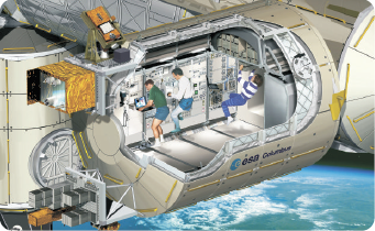
The ECLSS toolkit provides a set of components to design and analyze the usual equipment and processes of the Environmental Control and Life Support Systems in manned spacecraft. ECLSS modeling involves multi-disciplinary simulation, since ECLS operations consider a wide range of phenomena, including fluid flow, chemical and electrochemical reactions, heat transfer or biological processes. The toolkit is specially adapted to the thermo-hydraulic analysis of cabin air loops of conventional ECLS Systems. Specific fluid flow problems like venting lines or pressure regulators can also be analyzed easily, however. It could also be used for other applications like Submarines ECS and Aircraft ECS with treatment of cabin recirculated air.
The ECLSS toolkit is the recommended by European Space Agency (ESA) as the analysis tool for ECLS systems. It has been used in ESA projects to perform many different studies, including:
- Hydraulic and thermal analyses of the APM (Attached Pressurized Module) Cabin Air Loop for mode transition
- Hydraulic analyses of Multi Purpose Logistic Module (MPLM) cabin loop
- Simulation of the operation of the Refrigerator Freezer Rack’s (RFR) of the International Space Station (ISS)
- Design of venting lines for ISS
- Design of pressure regulators for the Oxygen/Nitrogen delivery to the ATV Cabin
- In addition, ESA developed specific EcosimPro libraries for the simulation of the Controlled Ecological Life Support System (CELSS) within the Micro-Ecological Life Support Alternative (MELISSA) project in order to understand the closed loop behavior and design the control system
The palette of components together with the intuitive EcosimPro/PROOSIS graphical interface offers a user-friendly drag-and-drop methodology to build new models. The input data editors help to configure the models. Thanks to EcosimPro/PROOSIS, the user can easily develop new components or modify the existing ones in order to achieve the required level of fidelity.
Main features:
- Wide variety of 1D-phenomena considered: fluid flow, chemical and electrochemical reactions, heat transfer, biological processes, etc.
- Thermodynamic functions to calculate fluid properties of:
- Perfect gas mixtures with or without water, which can change to liquid or solid phase.
- Real fluids like pure gases, water and pure liquid refrigerants.
- Coupling with the standard CONTROL and THERMAL libraries included in EcosimPro to model the process and thermal control systems.
- Ready to carry out preliminary designs of ECLS systems and determine off-design performances. Long duration transient analyses are simulated with reasonable CPU time consumption.
- Open code allowing modifications, inheritance, aggregation, encapsulation, etc., or new user-defined code.
- Easy-to-share models and multiple possibilities of interaction with external engineering software.
The library includes a complete palette of components that represent subsystems like the following:
- Cabins, represented by an air volume that takes into account deposition of condensed liquid water and ice and the evaporation of the water film on the cabin wall.
- Crew members with typical associated phenomena: metabolic activity, breathing, evaporative and heat losses from skin, skin blood flow, predictions of thermal comfort and thermal sensation, etc.
- Pipes, valves or sensors of different types with different levels of complexity to simulate fluid networks and their control loops.
- Other components of typical ECLS equipment such as pumps, fans, tanks, filters and models of more specific equipment such as chemical reactors, fuel cell stack, electrolyser, membrane, LiOH cartridges, etc.
This user case represents the temperature and humidity control of a spacecraft. The flow sheet of the main system of the user case model is shown in the following figure, indicating its main constitutive parts:
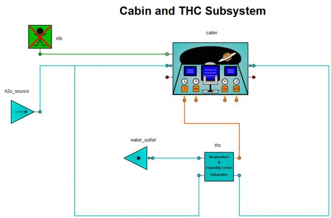
The system consists of the following parts:
- An “Inlet_w” component, labelled as “h2o_source”, that represents the water vapour produced by the crew and some equipment items.
- A “cabin” component, also labelled as cabin.
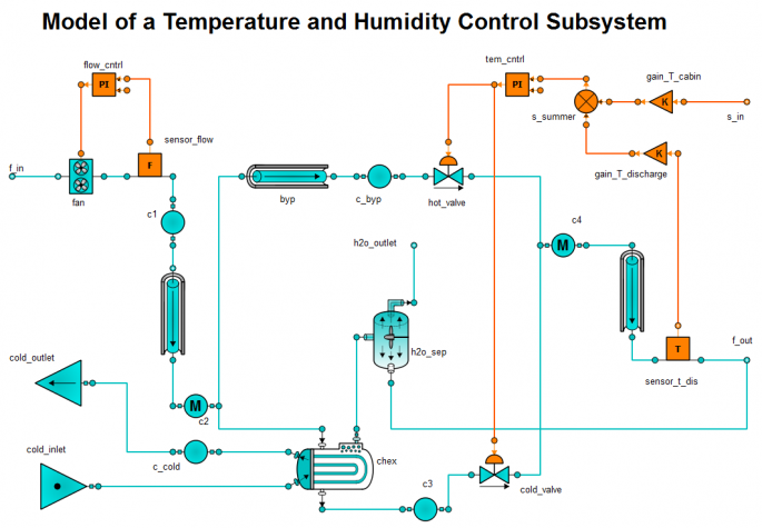
- A “thc” sub-system, also labelled as thc, the flow sheet of which is shown in the following figure.
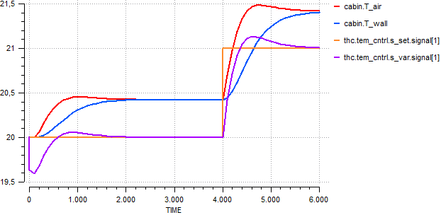
The experiment consists of a change of the temperature set-point with a step after 10 seconds. A steady state solution is requested before the transient solution in order to start the transient from a stabilised condition.
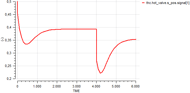
The following figures show the evolution of the temperatures in the cabin and the temperature measured by the sensor during the simulation (all the temperatures are showed in °C), and the position of the temperature control valve:
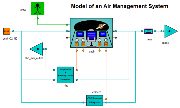
This user case represents the simulation of an Air Management System (AMS). It has been developed by integrating the following parts into one system:
- A “cabin” component.
- A “crew” component.
- A “THC” sub-system that represents the temperature and humidity control sub-system.
- A “co2rem” sub-system that represents the CO2 removal sub-system.
- A “cntrl_O2_N2” sub-system that represents an air controller.
- An “orifice” component that represents an air leak.
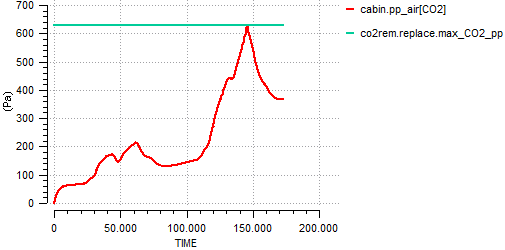
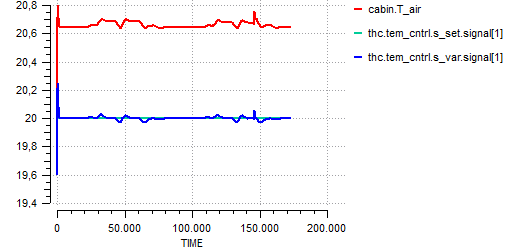
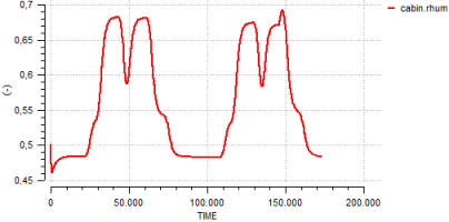
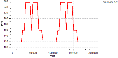
The experiment consists of imposing a daily cycle for crew activity, determined by the metabolic activity rate per crew member:
The following figures show the evolution of the CO2 partial pressure in the cabin air, the temperature in the cabin and the temperature measured by the sensor during the simulation (all temperatures in °C), and the relative humidity measured in the cabin air: