Alex Alexiou, National University of Athens (NTUA)
A new version of the TURBO library (4.0) is now available in order to improve the accuracy of transient calculations and further facilitate multi-disciplinary calculations within PROOSIS. In addition, a number of minor modifications have also been implemented to correct errors and improve component modelling and/or handling.
Transient modelling capabilities
Accurate prediction of gas turbine transient operation is important for stable operation, controller design and fault diagnosis. Transient simulations models should take into account a number of phenomena such as shaft and volume dynamics, heat soakage, tip clearance changes and control system delays and lags (e.g. of sensors, actuators, valves).
The previous version of the TURBO library accounted for shaft dynamics while heat soakage effects were only accounted in ducts and turbomachinery components through the Casing component. Heat transfer in the burner component and turbomachinery component blades and discs was not considered. The latter is also required in tip clearance calculations.
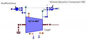
For modelling volume dynamics phenomena, a dedicated component (named VDC) is now available in the TURBO library. A switch allows the user to set the volume dynamics calculation on or off. Inside the VDC component the continuity, momentum and energy equations are employed in integral form to relate the flow quantities at the inlet and outlet of individual engine components. An example of its use is demonstrated in the following figure for the case of a compressor.
In order to obtain the metal temperatures of casing, disc and blades, the heat port in compressor, fan and turbine components are removed in the new version of the TURBO library and all heat soakage calculations are now performed within these components. The same approach (heat port removal) is also followed for the Duct component making this port redundant. Heat Soakage effects are also added in the Burner component.
Tip clearance calculations are now defined in compressor and turbine components. Correction scalars for isentropic efficiency and mass flow rate due to changes in tip clearance are based on the tip clearance change value and user-provided exchange rates.
Control
The control system receives pressure, temperature, rotational speed and fuel flow signals from the engine sensors. The previous version of TURBO library includes the Probe component which does not include sensor dynamics and is not compatible with the PROOSIS CONTROL library since a different port is used. For these reasons and in order not to affect backwards compatibility, a new set of components is developed for simulating sensors for total temperature (sensorTt), total pressure (sensorPt), static pressure (sensorPs), rotational speed (sensorN) and fuel flow rate (sensorWf). These components use the PORTS_LIB outlet analog_signal port to communicate with the control system while sensor dynamics are taken into account assuming first order lag. In addition, two components representing a basic fuel pump (fuelPump) and a fuel tank (fuelTank) are created.
Components with variable geometry have also been modified to accept control input signals. Variable bleed operation may occur both in compressors and ducts with bleeds. To model this operation, two additional options have been included in the relevant bleed type switch. Next, analog_signal inlet ports are added in duct and compressor components with bleeds. For the case of compressor variable stator vanes, an analog_signal inlet port is added in compressor components with map defined off-design performance. Next, the variable geometry switch is modified to include an additional option where variable geometry is present but modified according to the control signal.
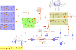
With the addition of sensor components and the modified variable geometry components, transient calculations can now be combined with an engine control system built entirely with components from the PROOSIS CONTROL library as shown in the following figure.
Other changes
In an effort to homogenize PROOSIS libraries, variables in the TURBO library use the UNITS of MATH library 3.2.1. In the same spirit, an interface component between the mechanical port of the TURBO library and that in PORTS_LIB is also available to allow connection of the relevant TURBO library components with components from other libraries. The RANGE directive is now used when declaring pressure, temperature, density and efficiency variables.
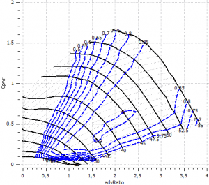
A new propeller component has been implemented that uses a map of power coefficient, efficiency and advance ratio for different blade angles and map auxiliary coordinate BETA. This map can now also be viewed in the Monitor. There is a new MFT pre-process procedure that does not require running the map generation experiment for plotting these maps in the Monitor. Following the modifications described earlier the Casing component and Heat, Sensor and BnSensor ports will be removed in future versions of the library (deprecated).
Finally, the TURBO library reference manual has been updated to reflect the new capabilities, improvements and corrections while a dedicated library is available that incorporates all the examples presented in the manual (TURBO_REF).


