By Victor Pordomingo. EcosimPro/PROOSIS Applications Team. EA Internacional
The creation of the ELECTRIC-SYSTEMS library is the final step towards completing the capabilities of PROOSIS. It can now simulate the aircraft engine (TURBO library) and complete the simulation together with the electrical system. This document shows the modelling of the aircraft (B767) engine and the electrical system, and focuses on the most relevant elements and the results for the main actuations under analysis: generator startup at no load, simultaneous connection of all the loads to check the limitations required by standard MIL-STD-704F, study of several short-circuits and the protections against them.
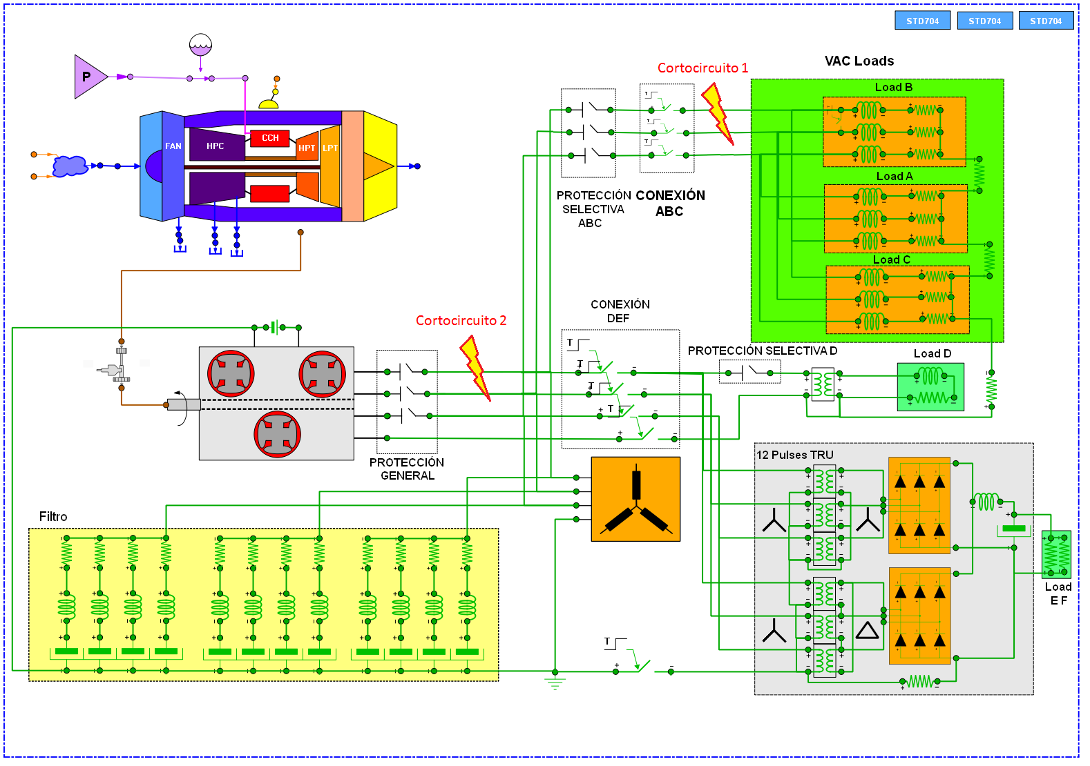 Figure 1. Aircraft Engine and Electric System PROOSIS model.
Figure 1 shows that the aircraft electrical system normally receives the mechanical power required to move the electrical generators from the engines propelling the aircraft themselves. This power is adapted to the needs of each load by means of electrical converters to supply the existing electrical loads in the system (DC, three-phase AC and single-phase AC).
In the aeronautical field, the electrical generators that are used are normally of synchronous type and will operate with a 200 V effective line connection at a frequency of 400 Hz. They will be Constant Speed Constant Frequency systems with a rotation speed of 12,000 rpm. These generators are normally of three-stage brushless type. They have been modelled in PROOSIS by means of the cascading of three common synchronous generators, as shown in figure 2.
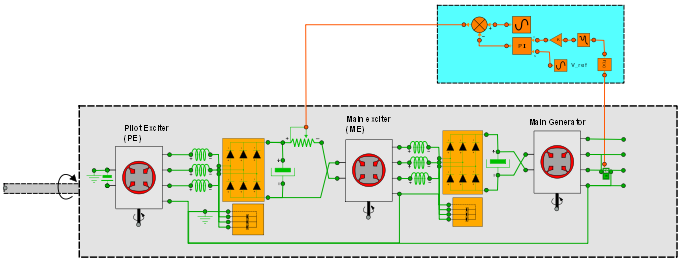 Figure 2. Three Stage Synchronous Brushless Generator.
At the same time, a transformer-rectifier unit is used to supply the DC loads in the aircraft. These rectifiers can be of several types, but the ’12 pulse’-type ones are the most common. Figure 3 shows the PROOSIS model of this unit. This type of converter has significant harmonic repercussions on the generated voltage. Their effects can be minimized by including a battery of tuned filters.
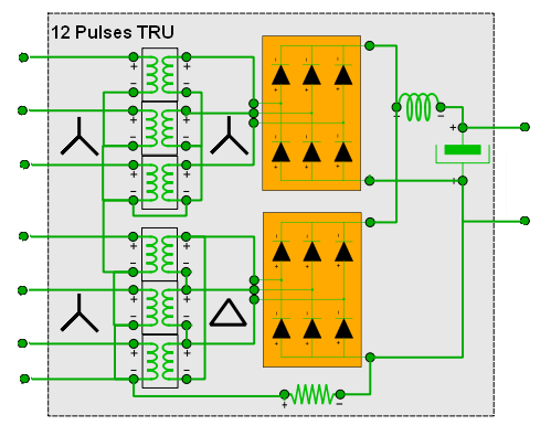 Figure 3. 12 Pulse Transformer Rectifier Unit.
The ELECTRIC-SYSTEMS library also allows short-circuits and protection systems to be modelled. To do this, there is a set of protection switches that can selectively isolate short-circuits or any other type of fault. To guarantee correct selective system operation, the points where the short-circuits have occurred need to be adequately isolated, depending on the location of the system malfunction. Protection switches with the appropriate configuration will be used. The boards can be designed by means of different current-time curves based on the estimated consumption in each part of the facility.
The whole model mentioned above can be used to analyse the aircraft propulsion system, electrical system and the mutual influences between them simultaneously so as to guarantee the stability of the assembly under the worst case scenario. Figure 4 shows the evolution of the phase voltage during startup and how it is kept within the limits set by Standard MIL-STD-704F.
 Figure 4. Phase voltages and limits in Standard MIL-STD-704F.
Figure 5 shows the evolution of the generated phase currents in effective terms with the connection of the whole load at TIME = 0.3 seconds, a short-circuit located downstream at TIME = 0.5 seconds and a short-circuit located upstream at TIME = 0.7 seconds.
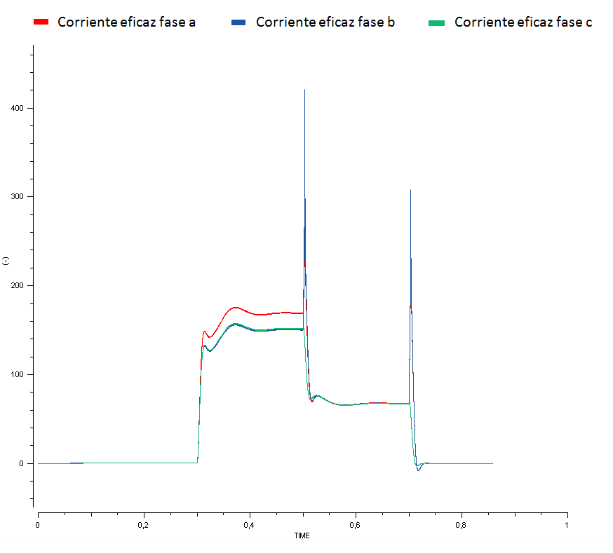 Figure 5. Generated phase current.