The ELECTRIC-PHASOR – the all-in-one toolkit for modelling and simulating electric and power systems. Perfect for large power systems, generation, distribution and Load-Flow calculations, this toolkit includes the wide use ELECTRIC-DQ library which presents main electrical components from a phasor point of view, making it easy to solve steady-state calculations. With components such as fixed and controlled voltage and current sources, linear loads, transformers and more, ELECTRIC-PHASOR is a versatile toolkit that can be used for both phasor modelling and complex models. Get accurate results at a higher level and for extended periods with the ELECTRIC-PHASOR Toolkit.
ELECTRIC-PHASOR toolkit has been created to solve a set of mathematical problems that arise when electrical components are analysed using differential equations (transient behaviour); mainly when the purpose for modelling and simulation is not to find out the dynamics of all the variables during each electrical transient, but rather to seek results at a higher level and for more extended periods (large power systems, generation, distribution, Load-Flow calculations, etc.).
ELECTRIC-PHASOR toolkit includes the ELECTRIC-DQ library and the user can find the necessary libraries and components for electric and power systems modelling and simulation using the phasor modelling approach to solve steady-state sine wave calculations.
The ELECTRIC-DQ library presents the main electrical components from a phasor point of view, assuming reference axes that rotate at the system’s frequency. Therefore, there is no transformation from sinusoidal systems to a vector representation. The advantage of the library is that it proposes phasor models from the beginning: in ELECTRIC-DQ, the amplitude of the vectors represents the peak value of the sine wave magnitudes.
Developing models only for phasor modelling or more complex models connecting this library to the CONTROL, MECHANICAL or ELECTRICAL libraries is possible.
Components
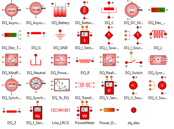
The available components in the ELECTRIC-DQ library are:
- Fixed and controlled voltage and current sources.
- Voltage, current and frequency sensors.
- Linear loads: Resistance, inductance and capacity.
- Single-phase and three-phase transformers.
- Power converter.
- DC machine.
- Synchronous unit with field excitation and permanent magnets.
- Asynchronous squirrel cage type and DFIG type unit.
- Calculation of symmetrical components.
- Signal converters.
The ELECTRIC-DQ library has a single generic Power Converter component. This component has been flexibly defined and can be configured to reproduce the behaviour of any typical topology.
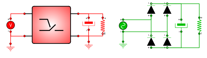
The following example describes how to simulate an ideal passive rectifier (AC/DC, Vout mode, Isolated load) in vector terms with ELECTRIC-DQ. At the same time, the simplicity of the example will help further your understanding of phasor modelling.
The schematic of the figure shows the structure of a passive rectifier feeding an isolated load modelled with the ELECTRICAL library (permanent sinusoidal regime) and the equivalent model with ELECTRIC-DQ.
Passive rectifier feeding a load with ELECTRIC-DQ and ELECTRICAL:
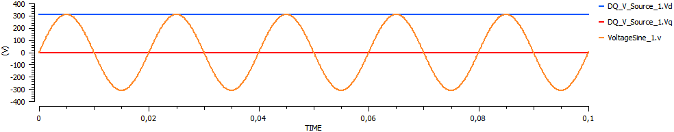
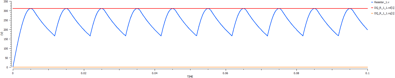
A default partition is created, which in ELECTRIC-DQ should always generate explicit models as it includes only linear loops. We perform a transient simulation to compare the constant vector values of ELECTRIC-DQ with the sinusoidal dynamic values of ELECTRICAL. The input and output voltages in both cases are shown in the following figure.
Input voltages in RPS (ELECTRICAL) and phasor (ELECTRIC-DQ):
Output voltages at the load in RPS (ELECTRICAL) and phasor (ELECTRIC-DQ):
The currents give us a clearer idea of the differences between transient sinusoidal and steady-state phasor modelling, especially when non-linear elements such as the diode are involved.
RPS (ELECTRICAL) and phasor (ELECTRIC-DQ) currents:
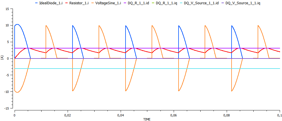
The output currents towards the load are equivalent (ignoring the ripple), although the phasor model does not allow you to calculate the detail transients of the current through each diode in each instant, nor its ripple, nor the dynamics of the capacitor. However, the transient model does not let you perform steady-state calculations due to the oscillatory nature of its variables nor does it allow you to reduce simulation times beyond a limit set by the time constants of the variables themselves, on the order of milliseconds.
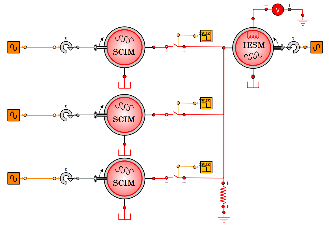
A synchronous machine with independent excitation works as an isolated generator to supply a load consisting of a set of four actuators modelled as induction motors. The expected behaviour is that the machine reaches a steady speed. In isolated mode, this speed determines the frequency of the local network, so any connected machines will rotate at the speed for that frequency.
Under normal conditions, the corresponding control loops would increase the mechanical torque that drives the synchronous generator and its excitation to ensure voltage and frequency in the grid. In this example, these control loops have not been included in order to show the correct behaviour of the machine models. In addition to the staggered connection of the machines, a mechanical load is applied simultaneously to all three actuators at TIME = 60 seconds.
Sincronous machine with ELECTRIC-DQ:
A default partition (explicit with linear loops) and a transient experiment are generated to study the dynamic evolution of all the variables in the model (the synchronous machine and the induction motors were all configured in transient mode in the schematic).
The first thing to study is the speed of each machine to confirm that they all behave as expected.
Generator and motor speed:
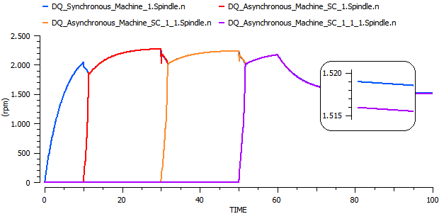
Initially, the asynchronous machine is the only one rotating thanks to the mechanical torque applied. At TIME = 10s the first motor is connected. The electrical load this entails makes the speed of the generator fall. The motor speeds up to the speed of rotation set by the generating frequency. The same sequence is repeated when the second machine is connected at TIME = 30s and when the third one is connected at TIME = 50s. Finally, the mechanical load is applied to the actuators at TIME = 60s.
The ELECTRIC-DQ models of the three-phase machines (transformer, induction machine and synchronous machine) are based on equivalent single-phase circuits, and therefore, balanced three-phase systems are assumed (constant dq components and zero component).
Unbalanced three-phase systems with connected rotating machines can be studied by using the symmetrical component technique. The ELECTRIC-DQ library has a component for carrying out these calculations. This component has been validated by comparing results in known cases. This example is only intended to illustrate the use of the DQ-Symmetrical Components component without entering into its validation.
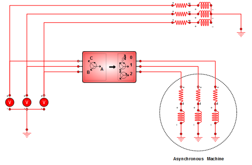
The following figure shows an example case in which an induction machine is connected to a three-phase system of unbalanced voltages and which, in addition, is loaded in parallel with an unbalanced load.
Induction machined connected to a three-phase system using ELECTRIC-DQ:
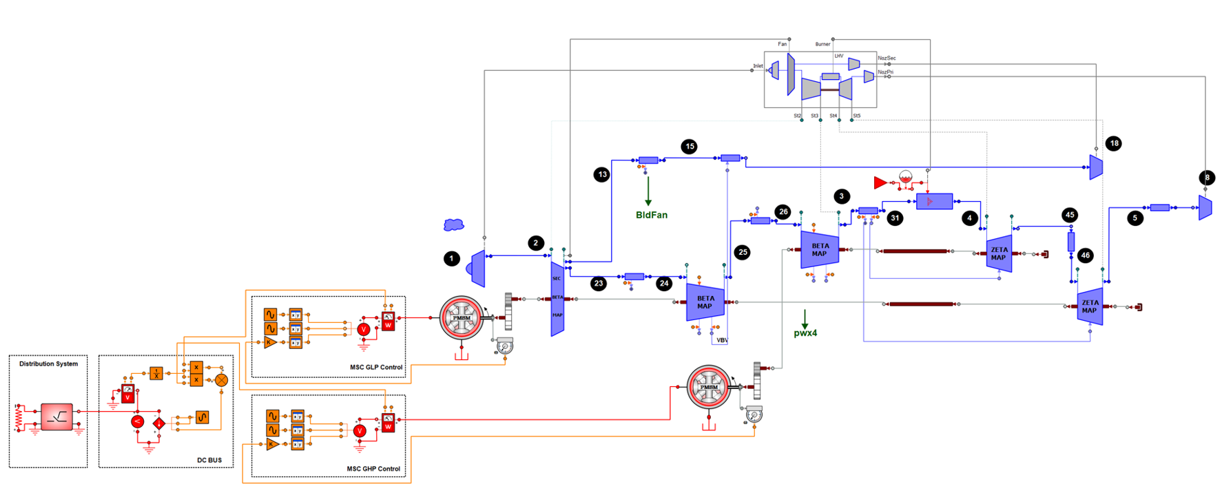
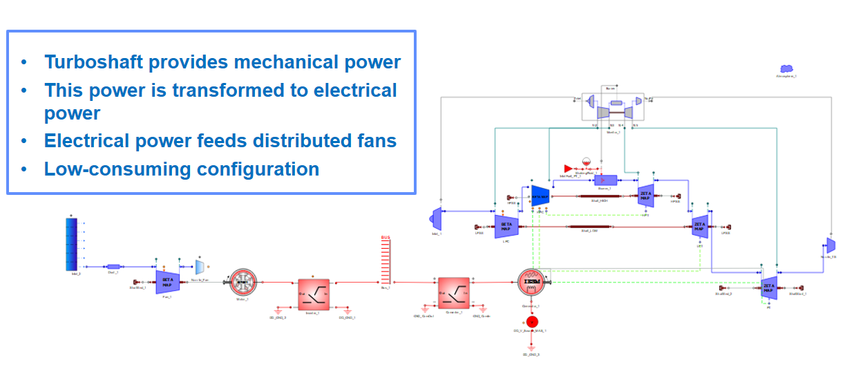
The toolkit allows the simulation of distributed aircraft propulsion systems. In these kinds of systems, the aircraft’s thrust comes from an array of electrically-fed small fans. A regular turboshaft provides the necessary mechanical power to feed an AC generator, which generates electrical power.
This power is afterwards transformed and distributed as high-voltage DC. A series of small electrical motors use this energy to move an array of propellers which are placed on a blended wing body.
The toolkit contains rotating AC and DC machines based on phasor modelling, which allows to perform very fast design/off-design and parametric calculations. Thanks to the high flexibility of the elements available in the libraries, it is possible to combine typical fuel-based architectures (turbofan, turboshaft, turboprop) with electrical propulsion devices (rotating machines, batteries), to build a cleaner and low-consuming propulsion solutions.
Distributed hybrid propulsion with ELECTRIC-DQ and PROOSIS:
More electric aircraft components can be simulated with PROOSIS. It is possible to do quasi-steady engine performance analyses combined with power extraction from the engine. Power can be extracted from the high or low-pressure shafts and, thanks to the presence of mechanical gearboxes, electric generators can be coupled mechanically. The global electric load (modelled with ELECTRIC-DQ) needed to feed auxiliary aircraft systems has significantly increased throughout the years, which makes essential the analysis of power generation together with the engine. The effect of power extraction in gas turbine turbomachinery can be checked, by considering different working scenarios and flight conditions. Slow dynamic effects (heat soakage, shaft inertia) are considered within the models.
More electrical propulsion with power extraction using ELECTRIC-DQ and TURBO Libraries: