The Aircraft System Simulation Toolkit include libraries for cycle analysis, steady and dynamic simulation of humid air systems, vapour cycles, hydraulic systems, and electric motor / generators. Its main libraries are the following:
- ACMS: Humid air cycles/management systems
- VCS: Vapor cycles systems
- LCS: Liquid cycle systems
- EPBS: Electric systems
ACMS Library
The ACMS library allows carrying out performance analysis and dynamic simulation of the Environmental Control System and other pneumatic systems of the aircraft.
The Environmental Control System (ECS) is the system responsible for performing a great number of tasks, including pressurizing and ventilating the cabin, controlling the pressure and temperature onboard, etc.
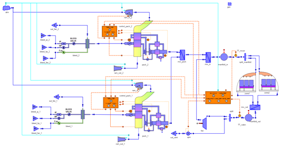
The ECS toolkit allows carrying out performance analysis and dynamic simulation of the Environmental Control System and other pneumatic systems of the aircraft.
The different sub-systems like the air cooling unit, the bleed system or control systems can be quickly modeled and simulated. The user can easily customize the cabin model, in terms both of number of zones and nodes as well as the distribution of passengers in the cabin.
The multidisciplinary capabilities of EcosimPro/PROOSIS and the ASYST toolkit allow performing, when necessary, complex simulations of the ECS model coupled with other systems, like the aircraft engine, electrical system, etc. For example, thermal management assessment can be performed by including in the model the fuel and oil system interacting through heat exchangers.
Key Features:
- Dynamic simulation & performance analysis of ECS
- Easy customization of the cabin layout
- Assessment of different architectures of cooling packs
- Analysis of the comfort of the passengers
- Easy customization or creation of new components
- Connection to other EcosimPro/PROOSIS toolkits (electrical, control, pneumatic/hydraulic, etc…)
- Connection to the aircraft engine model

VCS Library
The aim of this library is to calculate the thermodynamic design and off-design of vapor cycles, of an ORC (Organic Rankine Cycle), and to study the performance of the aircraft engine or other systems when coupled to the vapor system.
For example, an ORC system can utilize heat from engine exhaust gas to convert a fluid inside conduit into steam which can be transferred to a turbo-expander. The turbo-expander can be coupled to the engine shaft to transfer the converted energy to the shaft to allow the shaft to use less fuel to achieve the same power out, etc.
The components included in this library are designed to support different calculation modes: thermo-design and off-design. This means that the same components can be used for designing the equipment and selecting their parameters and also for simulating their behavior once the design is defined. This approach allows defining the thermo-design point for the components to provide support to size the components and to design the control of the system.
Features:
- The VCS library enables steady calculation and transient analyses caused by changes in the boundary conditions of the system.
- The working fluid is selected from a list of refrigerants defined in the library: R113; R245fa, R410a, R141b, water and ethanol.
- The thermo-physical properties of the working fluids are calculated using a REFPROP interface
- Mass and heat balances included in the components are always based on conservation laws, not considering the accumulation term in any of the components
- Components can be used in thermo-design mode or in off-design mode, just by switching an input parameter
- The components consider direct 0 D flow and do not take into account additional effects in other dimensions different from that followed by the fluid flow
- Different types of analysis can be performed:
- Steady state calculations
- Slow transient simulations changing the boundary conditions
- Parametric and optimization studies
This user case studies how the Environmental Control System of a commercial airplane evolves during a controlled descent of the aircraft.
Initial situation:
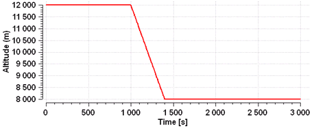
- Steady state run at cruise altitude of 12000 m (around 39000 ft)
- The target temperature of the cabin is 296.15 (23 ºC)
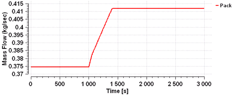
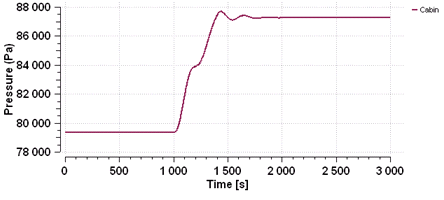
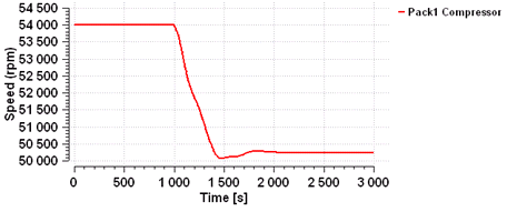
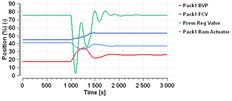
Transient scenario:
- At 1000 s, the aircraft loses altitude in a controlled descent down to 8000 m (around 26000 ft) in 400 s (rate of descent: 2000 ft/min)
- The cabin pressure is controlled according to flight altitude
- The temperature of the cabin is controlled to the target temperature during the descent
Results:
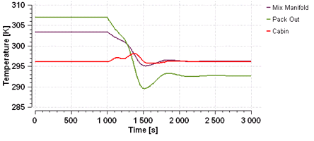
- During the descent, the ambient temperature increases. As a result, the cabin thermal losses decrease and the air temperature delivered by the cooling pack has to be lower
- The cabin temperature is controlled to the target value throughout the descent manoeuvre. It fluctuates within tolerable limits (less than 2ºC)
- The cabin pressure is controlled at higher values according to the pressurization schedule and, therefore, the air flow supplied by the cooling pack increases
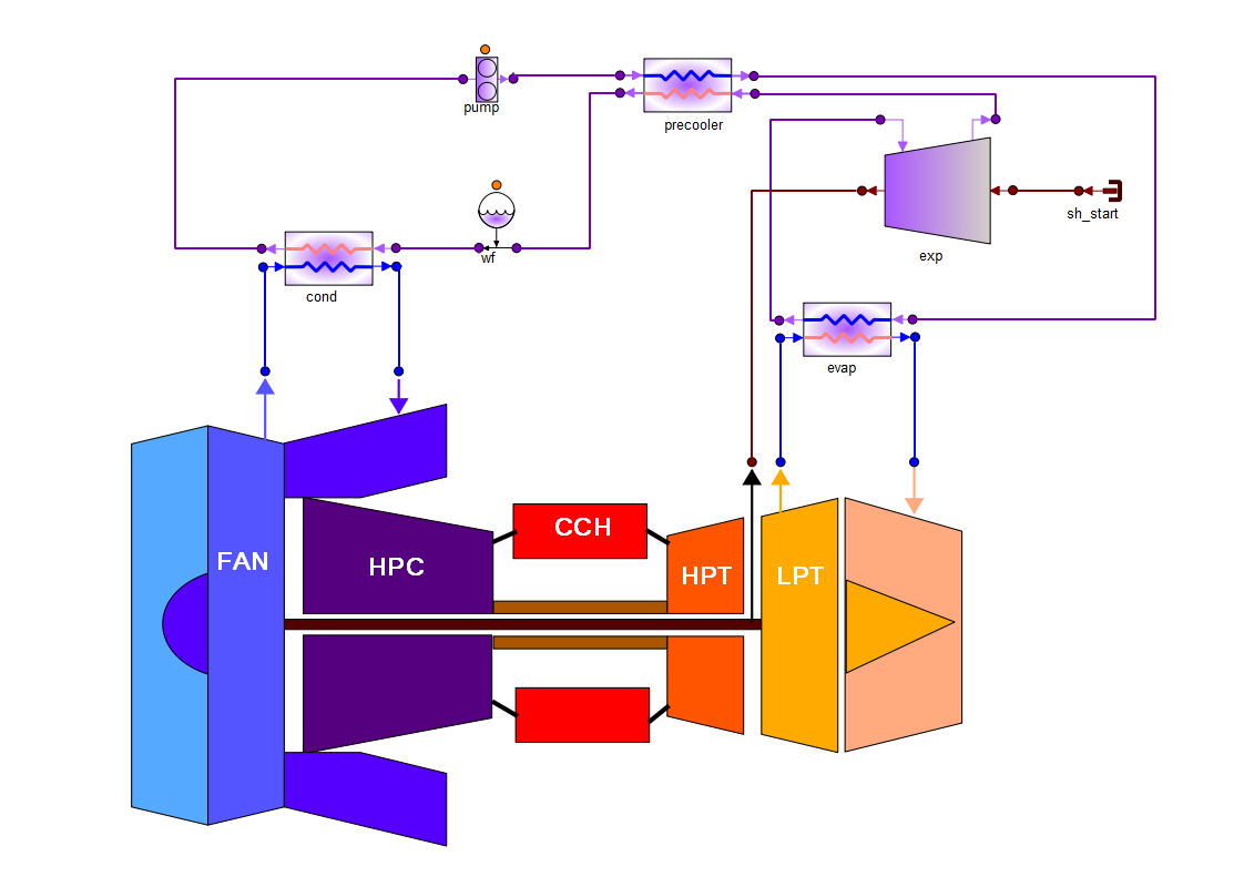
The model developed in this user case consists of an unmixed turbo-fan engine coupled to an ORC cycle heat recovery system. This system essentially recovers “waste heat” from the core jet exhaust of a turbofan engine and uses it to produce either electrical power or to transfer the converted energy to the low speed shaft reducing the fuel consumption required to accomplish the same power out.
The condenser is placed in the air bypass line of the aircraft engine and absorbs the heat transferred by the ORC fluid. The boiler is assumed to be placed within the core nozzle walls to extract heat energy from engine exhaust gases. The expander is mechanically coupled to the low speed shaft of the engine.
The ORC cycle includes a regenerator that enables the pumped liquid to absorb residual heat from expander outlet vapour prior to entering into the evaporator. The ORC uses R245fa as working fluid.
The schematics diagram of the complete model is shown in the following figure:

PROOSIS allows calculating the thermodynamic design of the engine and the ORC either separately or together. However, the typical procedure for the ORC integration in an aircraft engine starts with an already designed aircraft engine and continues by designing and optimizing the ORC cycle to the performance operation conditions of the engine.
Before the simulation of the integrated model, the thermodynamic design of the ORC system was performed considering cruise conditions for the aircraft interfaces.
Finally, the ORC model (in off design mode) was connected to the engine model and the performance of the overall model at different operation conditions was calculated in order to assess the feasibility and benefits of an organic Rankine cycle (ORC) heat recovery system for use in onboard aircraft power generation.
The main operation variables of the engine and ORC system have been plotted versus the altitude.
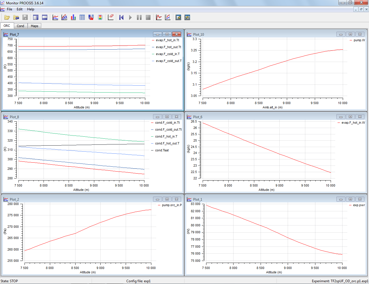
It is interesting to note that for the ambient and operation conditions assumed, the sub-cooling in the condenser decreases with altitude approaching the saturation condition. Thus, a control system would be required for regulating the outlet conditions of the ORC fluid at the outlet of the condenser.