The Environmental Control System (ECS) is the system responsible for performing a great number of tasks, including pressurizing and ventilating the cabin, controlling the pressure and temperature onboard, etc.
The ECS toolkit allows carrying out performance analysis and dynamic simulation of the Environmental Control System and other pneumatic systems of the aircraft.
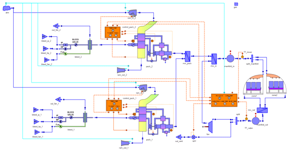
The different sub-systems like the air cooling unit, the bleed system or control systems can be quickly modeled and simulated. The user can easily customize the cabin model, in terms both of number of zones and nodes as well as the distribution of passengers in the cabin. ECS in combination with ECLSS toolkit could also be used for simulating different treatment processes of recirculated air in order to reduce the amount of fresh air required.
The multidisciplinary capabilities of EcosimPro/PROOSIS and the ECS toolkits allow performing, when necessary, complex simulations of the ECS model coupled with other systems, like the aircraft engine, electrical system, etc. For example, thermal management assessment can be performed by including in the model the fuel and oil system interacting through heat exchangers.
Key Features:
- Dynamic simulation & performance analysis of ECS
- Easy customization of the cabin layout
- Assessment of different architectures of cooling packs
- Analysis of the comfort of the passengers
- Easy customization or creation of new components
- Connection to other EcosimPro/PROOSIS toolkits (electrical, control, pneumatic/hydraulic, etc…)
- Connection to the aircraft engine model

This user case studies how the Environmental Control System of a commercial airplane evolves during a controlled descent of the aircraft.
Initial situation:
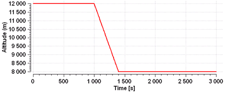
- Steady state run at cruise altitude of 12000 m (around 39000 ft)
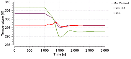
- The target temperature of the cabin is 296.15 (23 ºC)
Transient scenario:
- At 1000 s, the aircraft loses altitude in a controlled descent down to 8000 m (around 26000 ft) in 400 s (rate of descent: 2000 ft/min)
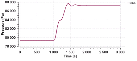
- The cabin pressure is controlled according to flight altitude
- The temperature of the cabin is controlled to the target temperature during the descent
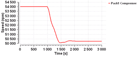
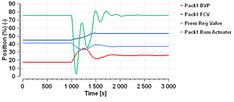
Results:
- During the descent, the ambient temperature increases. As a result, the cabin thermal losses decrease and the air temperature delivered by the cooling pack has to be lower
- The cabin temperature is controlled to the target value throughout the descent manoeuvre. It fluctuates within tolerable limits (less than 2ºC)
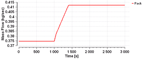
- The cabin pressure is controlled at higher values according to the pressurization schedule and, therefore, the air flow supplied by the cooling pack increases